Building the 8 bit computer
The following series of docs is a repository of my experience building (and possibly extending) the SAP-1 Ben Eater 8 bit breadboard computer.
This is Ben Eater's build, and what I will be attempting to build.
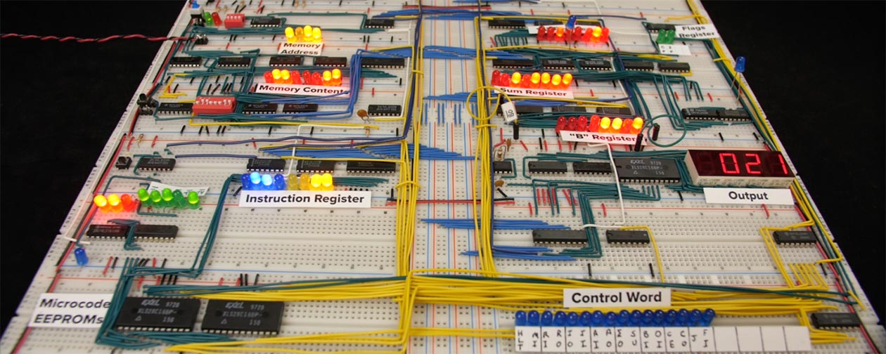 Image from https://eater.net/8bit/
Ben's 8 bit SAP-1 (Simple As Possible) itself is inspired by the SAP-1 description in the book Digital Computer Electronics Albert Paul Malvino And Jerald A Brown (here's a link to archive.org SAP-1 section of the book)
The modules are detailed below, each the page on each module may call out to blog posts for my "live" experiences. I'm building it slightly out of order compared to Ben's videos.
Additionally, Ben provides some very useful Kicad schematics on his website, but while reading them, I decided that another goal was to learn to create schematics myself. To that end, along side building the computer, I'm also drawing my own versions of the schematics in Kicad as I go. I find it really helps with my understanding of what's going on in each module because it forces me to consider more deeply than just connecting wires (plus, I gain a new skill).
Finally, there's a great community over on reddit. Make sure you go there.
Modules
1. Clock
The clock module that provides a clock signal out to the rest of the computer.
2. Registers A, B and IR
Two 8 bit registers (A, B) that can read and write to/from the bus and the ALU, and an Instruction Register that can read a 4bit op code and 4 bit memory address.
3. Power
Many posts on the web talk about power (see collated tips), so this page contains notes as I go about power distribution.
4. Bus
8 bit common data transmission lines that connect the modules, plus lines for Vcc, GND, Clock, Clear.
5. ALU
The ALU constantly sums (or subtracts depending on a control signal) the values stored in Register A and B, and optionally outputs that result to the bus.
6. Program Counter
The 4 bit program counter increments once per clock signal, with ability to output that value to the 4 least significant bits to the bus, and also read 4 least significant bits from the bus (to implement a jump). The counter represents the memory location that contains the current instruction. With a 4 bit program counter, that's a maximum of 16 memory addresses for the program (and the program needs to share that memory with program data, so not a lot of space!)
Memory Address Register
Coming soon...
Memory
Coming soon...
Manual memory programming
Coming soon...
Output Module
Coming soon...
Control logic
Coming soon...
Extension: Voltmeter & Ammeter
Based on reading others experiences, I know that power distribution around the board is an issue, so I added a cheap voltmeter and ammeter to the build, so that I could keep an eye on the power usage and voltage around the circuit.
Extension: Hex display
I also bought a pair of (rather expensive!) hex LED displays to output the BUS contents as values 00 to FF. No real functional reason, but I just felt like I'd like to also have a hex display rather than just binary 1s and 0s.
Tips I've learned
A variety of tips that I want to share based on my experience.
Other resources
Resources
I created a load of resources to help me with the build, including some printable chip wiring templates that I can overlay on the breadboards. I found them super useful to have the chip pinouts on the breadboard rather than keep having to refere to the datasheets.
Collated tips
This is a list tips I've read in various posts on reddit and elsewhere.
Kit contents
A list of the 4 kits from Ben's site, with links to the various datasheets for the various chips.
Other people's builds
A list of other people's builds that I found interesting.