5. ALU (Arithmetic Logic Unit)
Project Homepage: Building the 8 bit computer
The arithmetic logic unit takes two 8 bit binary inputs (from registers A and B), sums or subtracts the values, and outputs the result to the bus.
Moving on to the ALU, trying to plan out the wiring. I had drawn out my own version of the ALU in Kicad, so knew what needed to join to where. First I had a try of laying out the physical wiring in Fritzing, but that was just a painful mess.
ALU Template
One of the problems I have is translating my register output numbers (numbered from A0..A7 and B0..B7) into chip numbers (which would be numbered A1..A4 and B1..B4, repeated twice). So using the pinouts, I created a template that I can pin to the breadboard, and stop me needing to translate the pin numbers in my head.
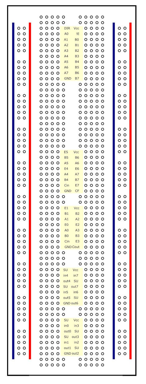
You can grab the inkscape SVG file here. It seems to come out the right size when printed on A4. Origial breadboard template here: http://code.rancidbacon.com/ElectronicBreadboardTemplates
It looks like this when attached to the breadboard:
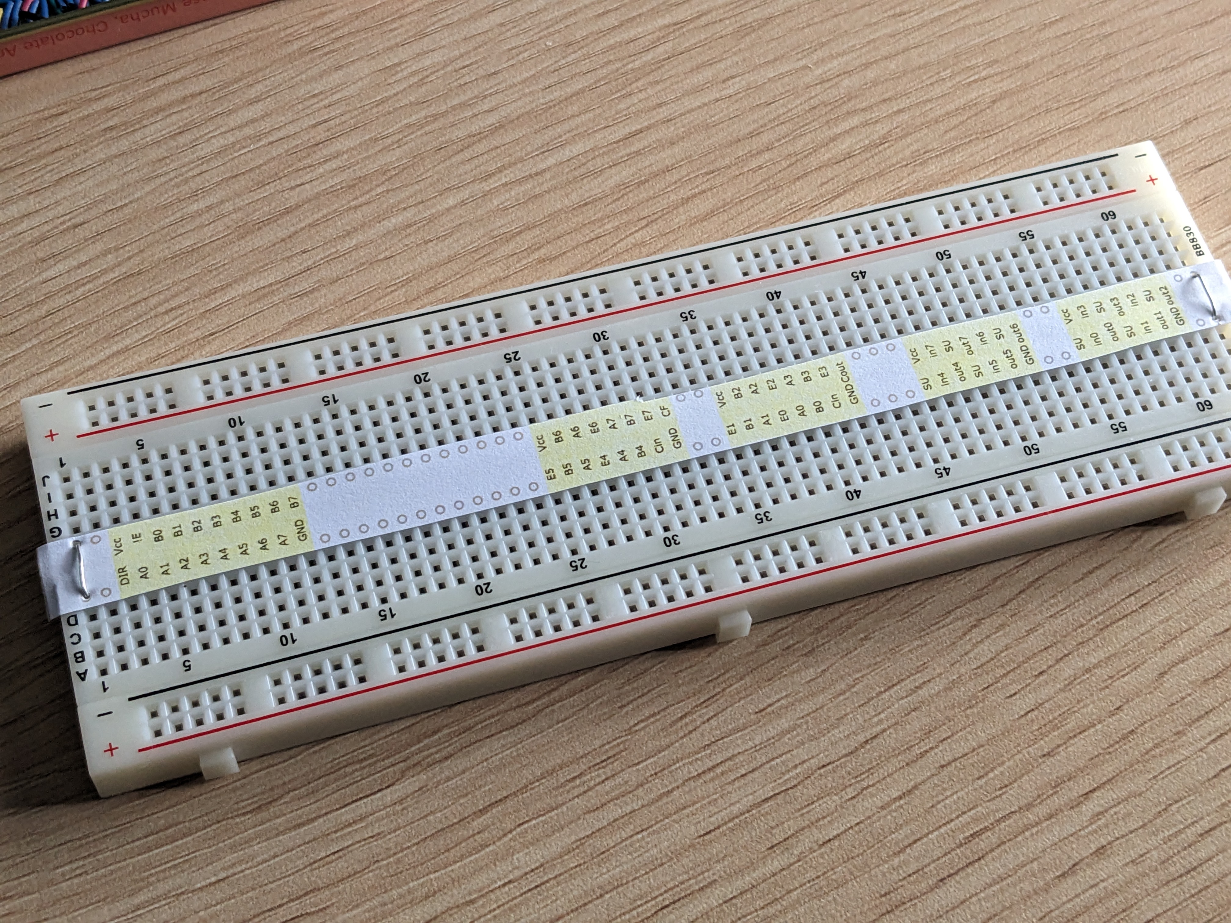
Notice that I've renumbered the pins to take into account being spread over two chips, so I can see exactly where the Reg A wires and Reg B wires should go in and out. Once I have the wiring in, I can remove the template and plug in the various chips.
Not sure where I'll put the lights... I'll work that out later, probably use a LED bar in the gap.
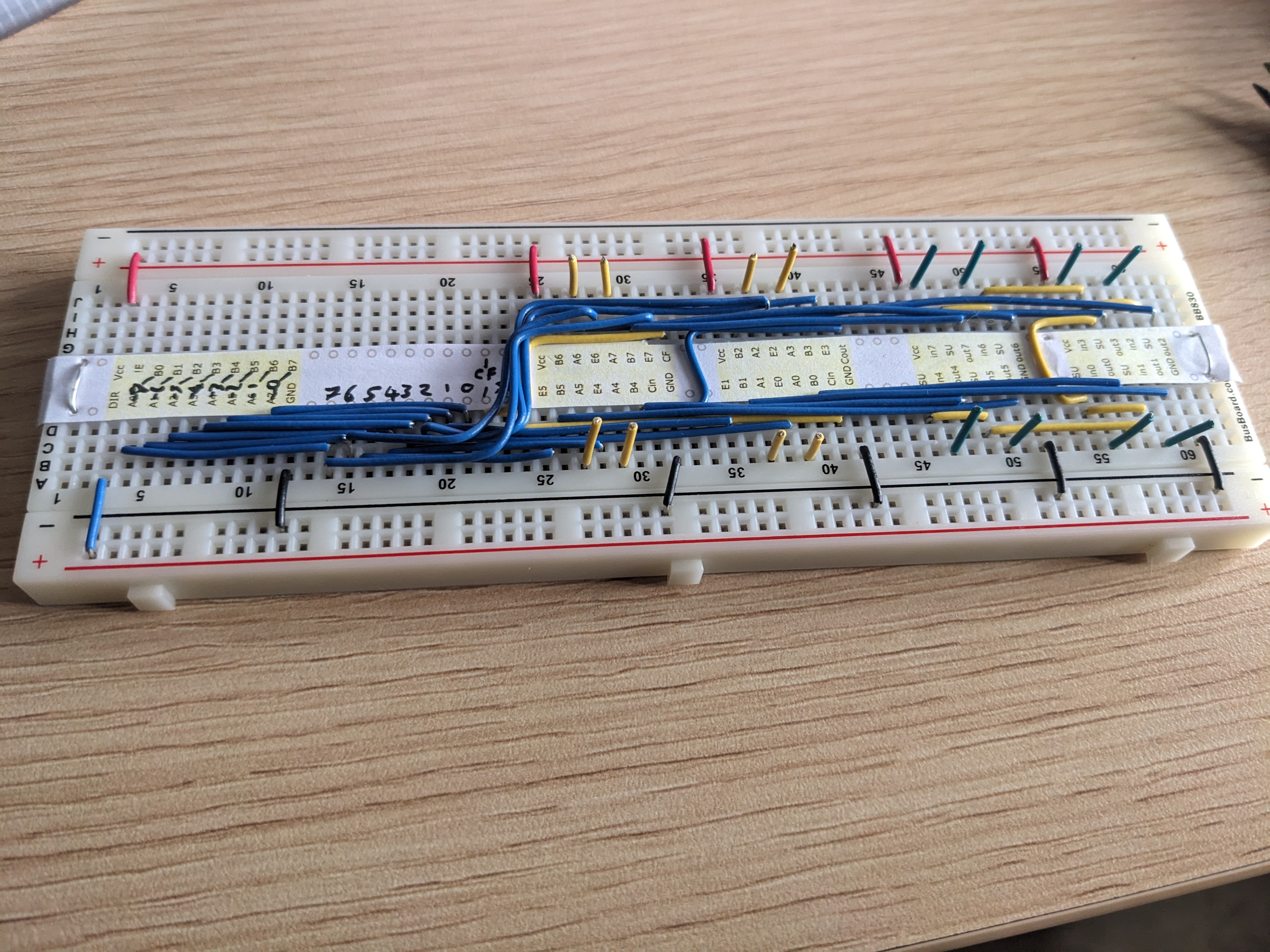
ALU Built
Below: Part wired ALU - this is all the internal wiring before I connect it up to the A and B registers, with yellow and green markers where the wires from the A (yellow) + B (green) will come in.
Below ALU with chips in place and registers waiting to be wired in, and a 10 LED array. The array is a Kingbright DC10SURKWA. Since writing this I've also got myself some resistor arrays to tidy it up a bit.
(2 days later...)
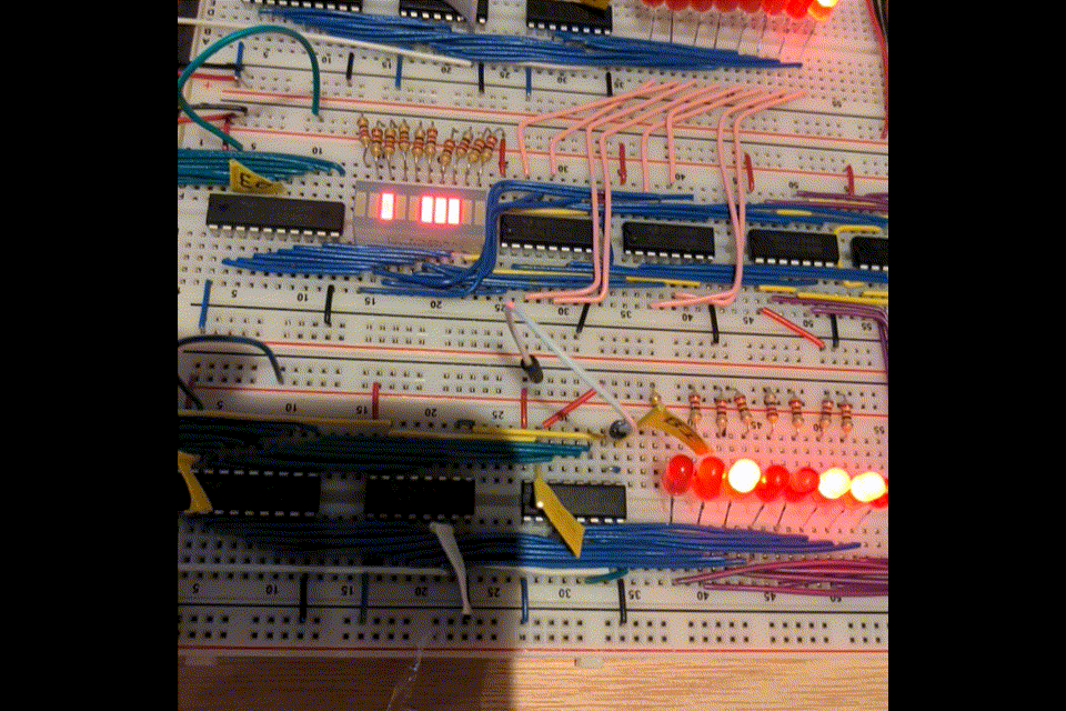
ALU Working
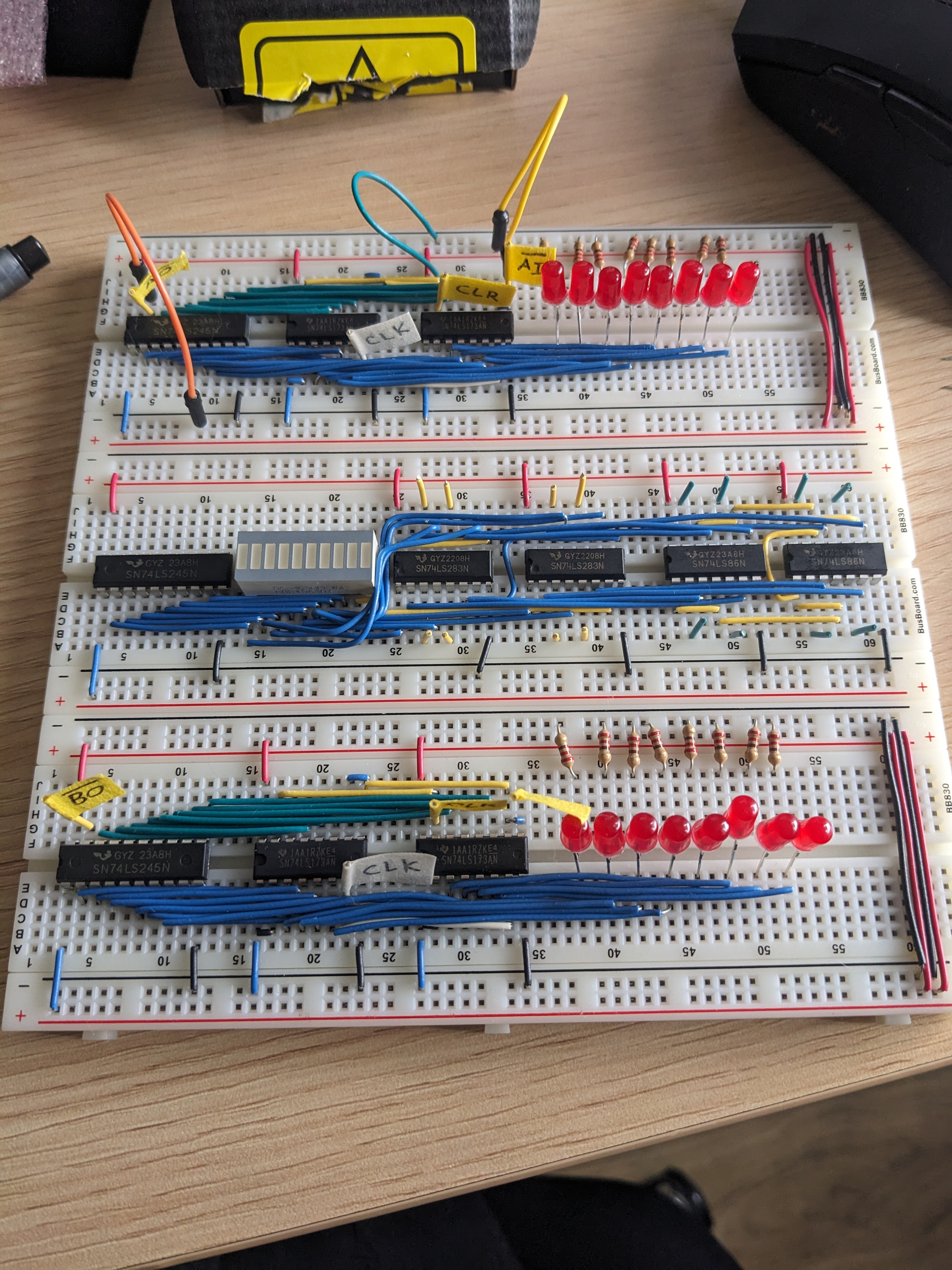
The ALU plus REG A and B are now wired into the bus. It adds numbers!

The LED array on the ALU has 10 LEDs, so I'm using the two least significant for other indicators (marked "ignore" on the photo) (specifically the Carry Flag output and the SUBTRCT input, I'll change the colours of them though in some future pass).
Here's a GIF of it incrementing numbers by 1. Achieved by setting Reg A data to 1, the AO (ALU Output to the bus) and BI (Reg B Input from the bus), so that on each clock tick, the Reg B reads what's currently on the bus, and the ALU puts the sum of Reg A and Reg B back onto the bus.