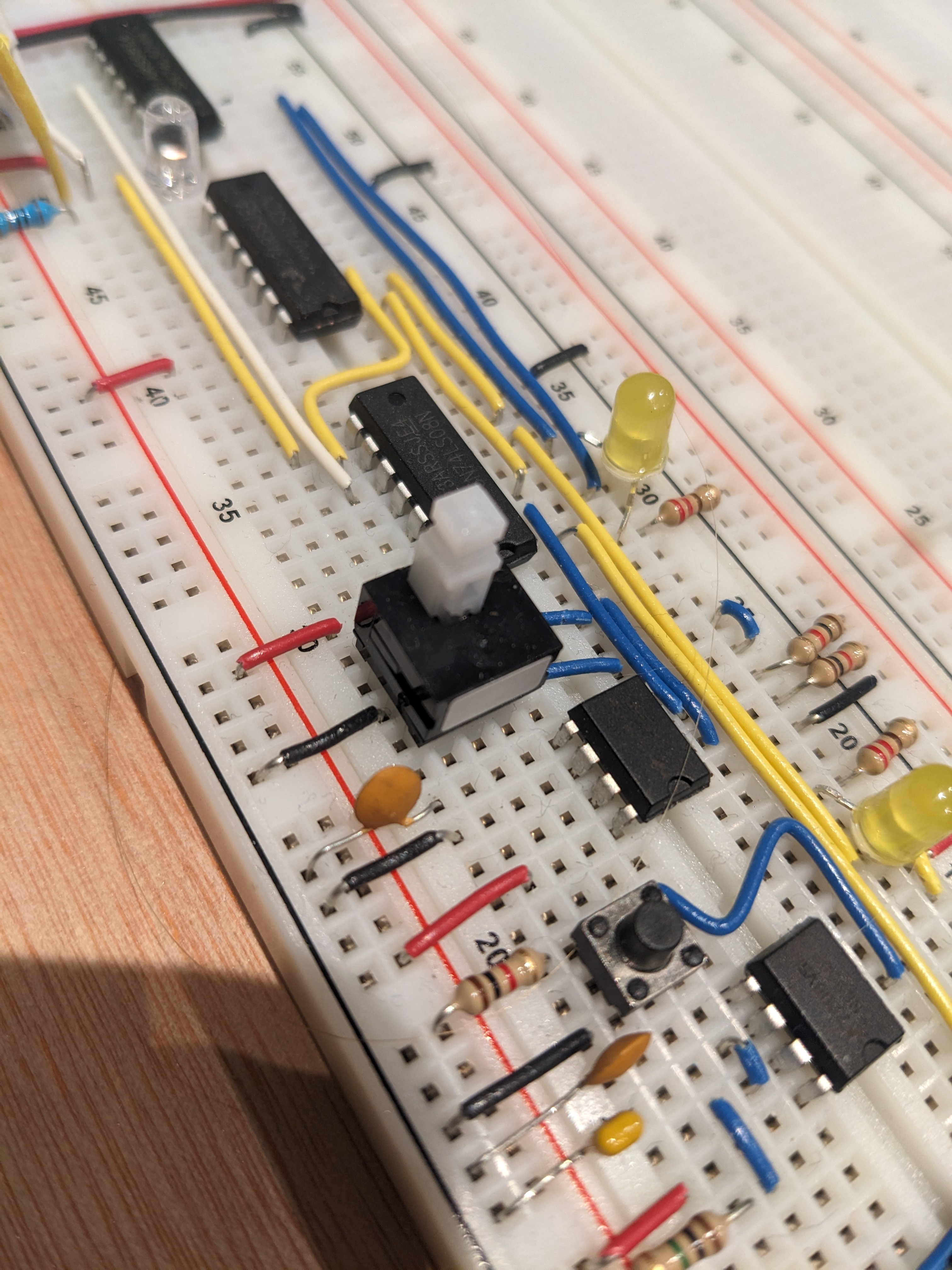
1. Clock
Project Homepage: Building the 8 bit computer
Building the clock module was my first attempt at breadboarding. Using the components in the kit was straightforward.
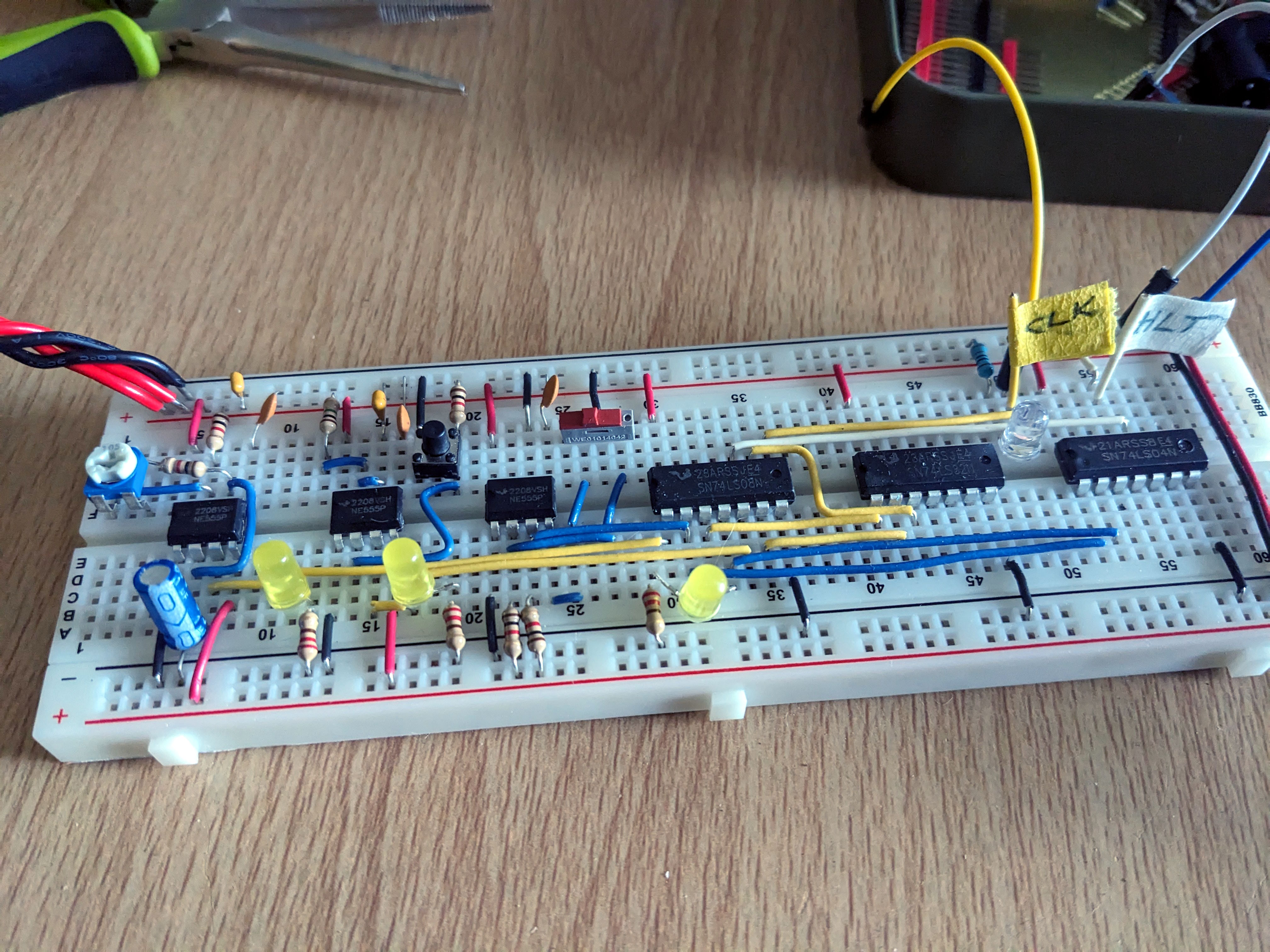
Clock module built, no immediate errors or problems apart from the slide switch supplied with the kit being the wrong size for the breadboard. My soldering wasn't great either, and although I got it to work by soldering some header pins, I ended up replacing it with a mini slide switch that fits nicely into the breadboard.

Although the slide switch worked well, it kept popping out when I slid it side to side, so I found an even better push switch alternative that fits straight into the breadboard.
Push switch SPPH110800 (mouser)
Wiring colours.
Something else I want to change is the wiring colours. I've sinced standardised on:
- Yellow -> Signal
- White -> Clock
- Blue / Pink / Purple -> Module wiring, primarily Blue, but Pink / * Purple when there is a real need to see the difference, eg ALU.
- Green -> Bus data
And of course:
- Red: VCC
- Black: GND
- But - I'm using Blue when I'm pulling a pin high to Vcc or low to GND.
So mostly on the clock, I want to change the pull up / down pins to blue, and switch round the white and yellow.