Chris's Resources
Project Homepage: Building the 8 bit computer
Resources created / used by Chris
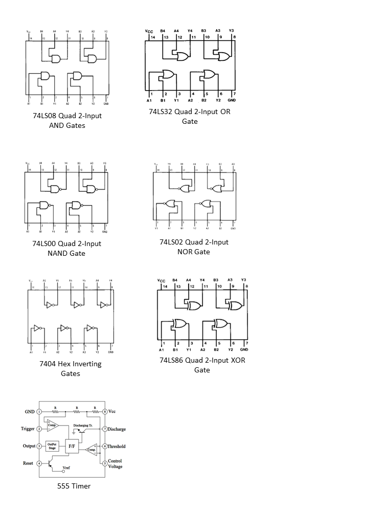
Logic chip pinouts
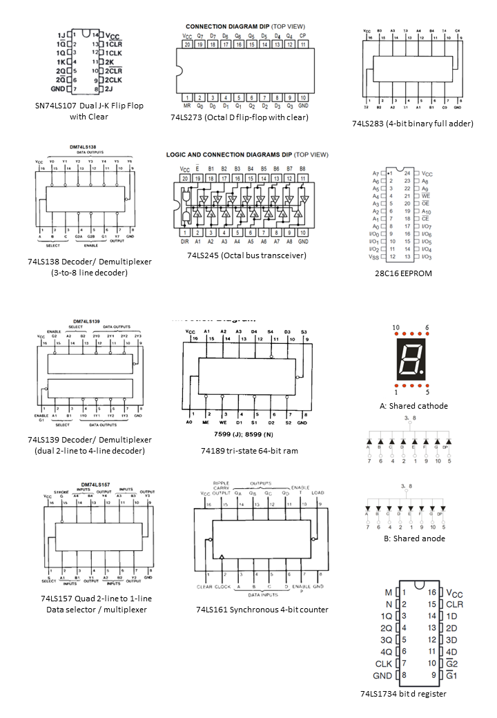
Other chip pinouts
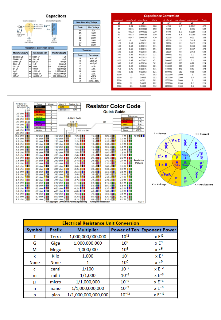
Units quick reference
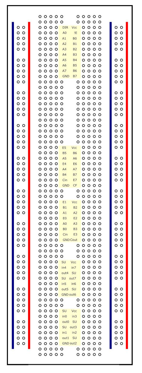
Inkscape SVG breadboard templates
I created these templates to give myself a hint on the breadboard as to which wires should go where. Generally the numbering matches up in some way. For example the pair of hex inverter chips at the bottom of the diagram below have in0 out0, in1, out1 through to in7, out7. From that I know that Reg B output 0 goes to the in0 on the inverter, and the out0 on the inverter goes to the B0 on the adder pair of chips in the middle (and likewise, out7 goes to the B7).
Later diagrams I started actually writing the chip numbers on them...
Here's an example of the ALU template:
Click the headings below to download the template svg for you to edit in Inkscape as you wish. When printing, the size seems to be right for A4 directly on inkscape; when I try and use PDF, it comes out a bit small.
ALU SVG Template
Click to open / download
Program Counter template
Click to open / download
Memory Address Register Template
Click to open / download
Memory Module Template
Click to open / download
Memory Programmer Template
Click to open / download